In the world of precision manufacturing, few components test a machine shop’s mettle like a hydraulic spool valve. To the untrained eye, it’s a shiny metal cylinder. To a mechanical engineer or procurement manager, it represents a minefield of potential failure points: concentricity issues, thermal distortion, and the nightmare of chatter on a slender shaft.
At Rapid Model, we see these designs daily. The part shown in the image above isn’t just a piece of turned metal; it is a textbook case for why CNC Turn-Mill Machining is superior to traditional sequential manufacturing.
Today, I want to break down the specific engineering challenges of this stainless steel component, analyze its features based on the visual evidence, and explain how we achieve sub-micron tolerances on parts that are prone to bending.
The Engineering Challenge: The “Slender Shaft” Problem
The immediate challenge with the component pictured is the Length-to-Diameter (L:D) ratio. When you have a part that is relatively long compared to its thickness, it behaves less like a rigid rod and more like a spring during machining.
As the cutting tool applies pressure, the material wants to push away. This deflection results in:
- Tapered geometries (the part becomes thicker in the middle).
- Chatter marks (vibration patterns on the surface).
- Poor Runout (the milled features are not aligned with the turned axis).
To combat this, we utilize advanced CNC Machining Services that integrate turning and milling into a single setup. By holding the part in a main spindle and supporting it with a sub-spindle or tailstock—and potentially using a Swiss-style guide bushing—we drastically reduce the unsupported length of the material.
Visual Analysis: Deconstructing the Spool Valve
Let’s take a technical look at the specific features of the stainless steel part in the image and what they tell us about the manufacturing process.
1. The Multi-Axis Geometry
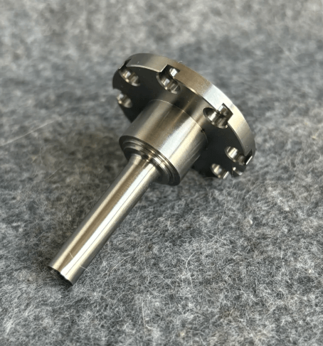
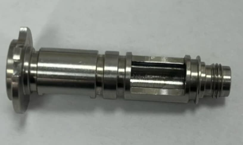
The part features a distinct flange on the left, stepped diameters, retaining ring grooves, and a threaded end on the right. However, the most critical feature is the rectangular pocket milled into the center shaft.
- The Problem: Milling a flat pocket into a round, thin shaft creates an “interrupted cut.” The tool enters and exits the material repeatedly, creating shock loads. On a thin stainless part, this induces heavy vibration.
- The Solution: High-speed milling spindles (20,000+ RPM) with variable helix end mills are used to break up harmonics. We likely machine this while the part is under tension between spindles to maintain rigidity.
2. Surface Finish and Sealing Surfaces
Looking at the reflection on the shaft, the surface finish is exceptional—likely in the range of Ra 0.4µm to 0.8µm.
- This suggests the part slides within a housing or bore, likely with O-rings seated in the grooves.
- Any scratch or chatter mark here would lead to hydraulic fluid leakage or seal failure.
- Achieving this straight off the machine requires precise wiper inserts, but often, we apply secondary Surface Finishing techniques like electropolishing or centerless grinding to ensure a mirror-like seal interface.
3. Material: The Stainless Steel Factor
The color and luster indicate this is likely Stainless Steel 304 or 316L. While excellent for corrosion resistance, these materials are notorious for work-hardening. If the tool dwells in one spot for even a fraction of a second too long, the material hardens, destroying the tool edge and ruining the dimensional accuracy.
- Strategy: We use high-pressure coolant (1000 PSI+) to evacuate chips immediately and keep temperatures consistent, preventing thermal expansion from altering the tight tolerances.
Why Single-Setup “Turn-Mill” is Non-Negotiable
In the past, this part might have been turned on a lathe, taken out, fixtured on a mill for the pocket, and then threaded. That is a recipe for disaster.
Every time you unclamp and reclamp a part, you introduce stack-up error. For a spool valve, the runout between the bearing surfaces and the central milled pocket must often be within 0.01mm (0.0004″).
With modern Turn-Mill centers (or Swiss Lathes for diameters under 32mm), we perform:
- Turning (OD profiling)
- Grooving (O-ring seats)
- Milling (The central pocket)
- Threading (The right-side interface)
All in one grab. This guarantees that the geometric relationship between the milled pocket and the turned axis is perfect.
From Rapid Prototype to Mass Production
Whether you are in the design verification stage or ramping up for product launch, the consistency of the machining strategy matters.
For Rapid Prototyping, we use the same CAM programming strategies as we do for production. This means the prototype you receive behaves exactly like the final production part. We don’t “cheat” the prototype with softer materials or looser tolerances just to get it out the door fast.
The Rapid Model Advantage
At Rapid Model, we specialize in high-complexity, low-to-mid volume manufacturing. We understand that a drawing tells us the dimensions, but the function of the part tells us how to machine it.
- ISO 9001 Certified: Full traceability on materials.
- 5-Axis & Swiss Capabilities: We have the equipment to handle slender parts without deflection.
- Metrology: Every critical valve component undergoes CMM inspection to verify concentricity and profile tolerances before shipping.
If you are designing complex shafts, valves, or medical devices that require tight runout control and superior surface finishes, you need a partner who understands the physics of machining.
Ready to validate your design?