In the world of precision engineering, straight lines and prismatic shapes are straightforward. They are easy to measure, easy to clamp, and easy to machine. But the human hand is not square. When designing parts that interact with the human body—like brake levers, medical device handles, or consumer electronics—engineers must prioritize ergonomics.
However, transitioning from a CAD spline to a physical, machined part often leads to a common defect: faceting. This is where a curved surface appears as a series of small flat polygons rather than a smooth arc.
At Rapid Model, we see this challenge daily. Today, I want to break down the specific machining strategies we use to achieve liquid-smooth finishes on complex, organic shapes, using a recent project as a case study.
Table of Contents
- The Challenge of Organic Geometries
- Visual Analysis: The “Matte Grey” Levers
- CAM Strategy: Scallop Height and Step-Over
- Surface Finishing: The Science of the Matte Look
- Why Rapid Model for Complex Geometries?
The Challenge of Organic Geometries
When a designer sends us a STEP file for a part with compound curves, standard 3-axis machining strategies often fall short. If the toolpath is not optimized, the cutter leaves behind “cusps”—small ridges of material between passes.
To remove these cusps usually requires aggressive hand-sanding, which destroys the dimensional accuracy of the part. If you are designing a high-performance mechanical lever, you cannot afford to have the pivot point altered by manual polishing.
To solve this, we utilize advanced CNC Machining Services that leverage 5-axis simultaneity. By rotating the part while the tool cuts, we maintain the optimal cutting angle of the ball-nose end mill relative to the surface normal. This ensures constant cutting velocity and surface finish consistency across the entire curve.
Visual Analysis: The “Matte Grey” Levers
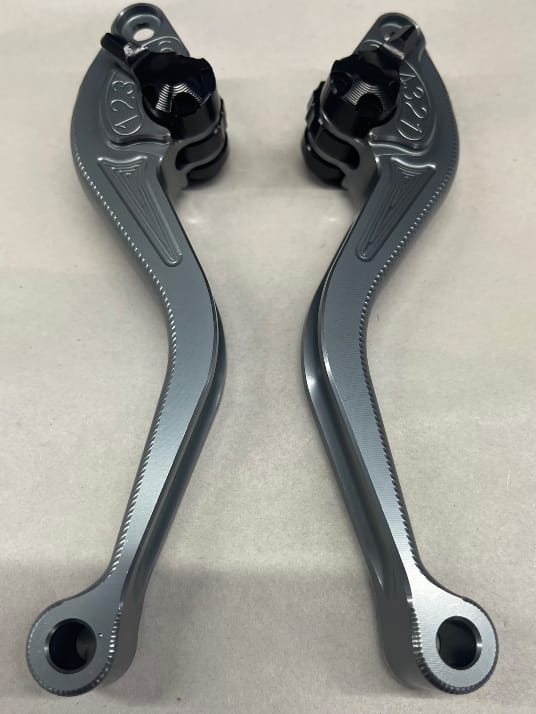
Let’s look closely at the image provided above. These are high-performance adjustable levers, likely for a motorcycle or high-end mountain bike application.
Material Identification:
Based on the finish and application, this is almost certainly Aluminum 6061-T6 or 7075-T6. 7075 is often preferred for levers due to its higher tensile strength, preventing snapping under emergency braking loads.
Key Features & Machining Nuances:
- The Ergonomic Sweep: The main body of the lever features a compound curve (S-shape) designed to fit the finger radius. Notice the lack of “chatter” marks. This indicates a highly rigid setup during machining.
- Grip Texture: On the front face, you can see fine, machined grooves running parallel to the lever’s length. This isn’t a defect; it is a functional design feature added to increase friction for the rider’s gloved finger.
- Precision Assembly: The black anodized adjuster knob (assembled with the grey body) implies tight tolerance requirements (H7/g6 fits) to ensure the mechanism clicks firmly without wobbling.
- Engraving: The numbers (1, 2, 3 / 4, 3, 2, 1) are milled directly into the curved surface. This requires “surface mapping” in the CNC program to ensure the engraving depth remains constant as the surface curves away.
CAM Strategy: Scallop Height and Step-Over
How do we achieve that smooth surface before the part even hits the finishing department? It comes down to the Step-Over.
In CNC terminology, the step-over is the distance the tool moves sideways between passes.
- Large Step-Over: Faster machining time, but leaves high “scallops” (rough ridges).
- Fine Step-Over: Slower machining time, but results in a near-polished surface.
For the levers shown above, we utilized a Ball Nose End Mill with a micro-fine step-over (likely under 0.05mm). This technique creates a surface roughness (Ra) low enough that the subsequent bead blasting completely blends the tool marks, rather than just hiding them.
If you are in the development phase, we recommend utilizing our Rapid Prototyping services to test different surface textures. We can machine one lever with a smooth finish and another with knurling to let your team physically feel the difference before committing to mass production.
Surface Finishing: The Science of the Matte Look
The premium “tactical” look of these levers is not painted; it is an electrochemical process.
1. Bead Blasting:
Before anodizing, the raw aluminum parts are bombarded with glass beads or ceramic media. For these levers, we likely used a #120 grit glass bead. This unifies the surface tension and removes any microscopic directionality from the machining process, resulting in a non-reflective, satin finish.
2. Type II Sulfuric Anodizing:
The parts are then submerged in an electrolytic bath. The grey color is achieved through organic dyes absorbed into the porous oxide layer before sealing. This provides:
- Corrosion Resistance: Vital for outdoor parts exposed to rain and road salts.
- Surface Hardness: Prevents scratches from keys or gloves.
Engineers often struggle to define these requirements on technical drawings. A simple note of “Anodize Grey” is insufficient. For results like this, you should specify: “Bead Blast 120 Grit, Anodize Type II, Matte Grey, Seal.”
For a deeper dive into available textures and coatings, visit our Surface Finishing guide.
Why Rapid Model for Complex Geometries?
At Rapid Model, we don’t just load code and hit the green button. We analyze the function of the part.
- 5-Axis Capabilities: We machine complex undercuts and organic shapes in a single setup, improving accuracy.
- In-House Metrology: We verify the pivot points of levers using CMM (Coordinate Measuring Machines) to ensure the assembly will function smoothly.
- Speed: Located in the heart of Shenzhen’s manufacturing hub, we can source aerospace-grade aluminum and turn around complex prototypes in as little as 3 days.
Whether you are building robotic end-effectors or automotive interiors, the difference between a “good” part and a “premium” part is usually in the surfacing strategy.
Ready to bring your ergonomic designs to life?
Stop settling for faceted curves. Let’s discuss your project requirements.