In the world of high-precision manufacturing, it is often what is on the inside that counts.
For product designers and mechanical engineers, designing a sleek, ergonomic handheld device is the goal. But for the manufacturing floor, that design often translates into a complex challenge: Thin Wall CNC Machining.
Recently, our team at Rapid Model tackled a project that perfectly illustrates the delicate balance between design aesthetics and structural integrity. The part—a split-housing handle for an electronic device—featured complex geometry, deep pockets, and wall thicknesses dropping below 1mm.
If you have ever sourced machined parts, you know the nightmare scenarios associated with these specs: vibration, chatter marks, deformation, and mating lines that don’t align.
In this post, I will break down how we achieved a flawless result on this project, analyzing the specific challenges visible in the part and the engineering strategies we used to overcome them.
Table of Contents
- Visual Analysis: Anatomy of a Split Housing
- The Enemy of Precision: Vibration and Chatter
- Strategic Material Removal: The “Onion Skin” Technique
- The Critical Seam: Achieving Perfect Mating Surfaces
- Surface Finishing: The Final Touch
- Why Rapid Model?
Visual Analysis: Anatomy of a Split Housing
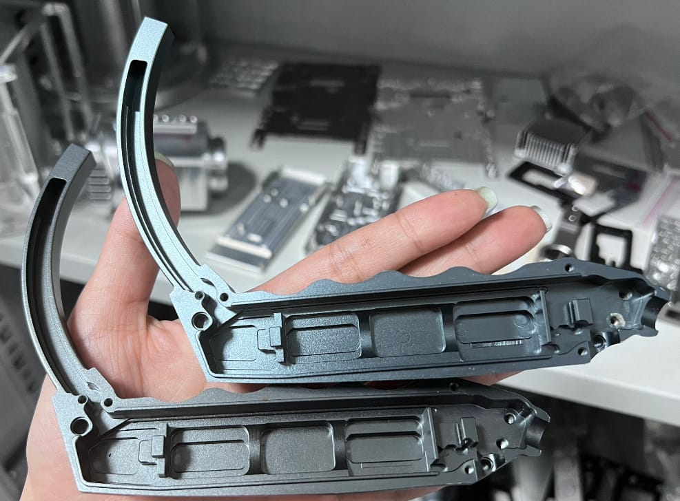
Let’s take a closer look at the image above. I am holding the two halves of the machined housing (the “clam-shell”). From a manufacturing perspective, several features immediately stand out that dictate our machining strategy:
- Complex Internal Pocketing: You can see distinct ribs and bosses inside the main body. These aren’t just for weight reduction; they provide mounting points for internal electronics and structural rigidity to the outer shell.
- The Curved “Neck”: The upper portion of the handle features a long, slender curve. This is the danger zone. With no internal support ribs in this area, the aluminum is highly susceptible to deflection during cutting.
- Variable Wall Thickness: While the mounting points are robust, the walls surrounding the electronics cavity are incredibly thin—less than 1mm in some areas.
- Finish Quality: The part has a uniform matte grey finish, indicating a post-machining surface treatment designed to hide tool marks and provide a tactile grip.
To produce this via CNC Machining Services, we cannot simply clamp a block of aluminum and cut aggressively. We need a strategy.
The Enemy of Precision: Vibration and Chatter
The primary challenge mentioned in the project brief was vibration.
When machining thin-walled aluminum (typically 6061-T6 or 7075), the material acts almost like a tuning fork. As the end mill engages with the material, the thin wall wants to push away (deflect) and then snap back. This oscillation causes “chatter”—that distinct, ugly ripple pattern on the surface of the part.
Chatter isn’t just cosmetic; it ruins dimensional accuracy. If the wall vibrates during the final pass, your tolerance goes out the window.
How We Solved It:
- Low Cutting Forces: As noted in the project summary, we utilized low cutting forces. This involves using sharp, high-helix angle end mills (often 3-flute for aluminum) which shear the material rather than pushing it.
- High RPM, Low Step-Over: We increased the spindle speed but reduced the radial depth of cut (step-over). This reduces the load on the wall, keeping the heat in the chip rather than the part.
- Custom Soft Jaws: You cannot hold this part in a standard vise. We machined custom soft jaws (fixtures that mirror the part’s negative shape) to support the thin walls from the outside while we machined the inside.
Strategic Material Removal: The “Onion Skin” Technique
When you remove a large volume of material from a block of aluminum, you release “residual stress.” This causes the material to twist or warp naturally.
For a part like this split handle, if we machined one side to completion and then flipped it, the part would likely curl like a potato chip.
To prevent this during the Rapid Prototyping stage and production, we often use an iterative approach. We rough out the material on both sides, leaving a small buffer stock (0.5mm). We then let the material “relax” before coming back for the final finishing passes.
For the thinnest areas (<1mm), we sometimes employ “onion skinning”—machining the wall to final depth in axial layers, ensuring the cutter is always supported by the material below it until the very last moment.
The Critical Seam: Achieving Perfect Mating Surfaces
Look at the edge of the handle in the photo. That perimeter is the “mating surface.” Since this is a split housing, those two halves must come together with zero visible gap.
If the thin wall warped during machining, you would see a “seam line” or a step when the device is assembled. This is unacceptable for high-end electronics.
To ensure a seamless fit:
- Flatness Tolerance: We maintain a flatness tolerance of +/- 0.05mm on the mating perimeter.
- Pin Alignment: You will notice small holes on the mating face. These are for alignment pins or screws. We bore these holes in the same setup as the perimeter contouring to ensure perfect concentricity.
Surface Finishing: The Final Touch
A beautiful exterior starts with a stable interior, but the surface finish is what the end-user actually feels.
The parts in the photo showcase a classic Bead Blasted and Anodized finish.
- Bead Blasting: We bombard the surface with fine glass beads (likely #120 grit). This removes minor machining lines and creates a uniform, non-reflective texture.
- Anodizing (Type II): The grey color comes from the anodizing process, which increases corrosion resistance and surface hardness.
However, finishing thin walls requires care. Aggressive blasting can actually warp a 1mm aluminum wall. We adjust our blasting pressure to ensure the finish is consistent without compromising the geometry.
Explore more about our textures and colors on our Surface Finishing page.
Why Rapid Model?
Machining a solid block is easy. Machining a lightweight, thin-walled, split-housing that snaps together perfectly? That requires engineering expertise.
At Rapid Model, we don’t just run tool paths; we analyze the geometry.
- ISO 9001 Certified: Our processes are documented and consistent.
- Advanced Equipment: We utilize 5-axis CNC machines that allow us to reach deep pockets and complex curves without multiple setups, reducing error stacking.
- Design for Manufacturing (DFM): Before we cut a single chip, we review your CAD files and suggest optimizations to reduce chatter and cost.
If you are developing a handheld device or an electronic enclosure, don’t let thin walls limit your design. Let us handle the vibration, so you can handle the innovation.
Ready to start your next project?