In the world of custom manufacturing, there is a distinct difference between “possible” and “repeatable.”
When you send us a CAD file for a single prototype, the challenge is geometric: How do we hold the part? What tool paths will create this feature? However, when that order shifts to a batch of 500 or 1,000 units, the challenge shifts from geometry to process stability.
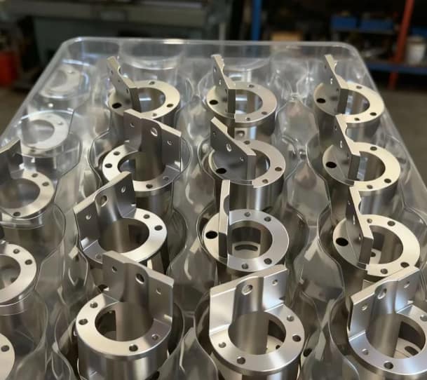
Looking at a tray of freshly machined parts—like the aluminum housings shown in the image above—gives a sense of calm. But for a Mechanical Engineer or Procurement Manager, that image should represent something else: statistical process control.
In this post, I will break down the specific machining challenges visible in these aluminum housings and explain how Rapid Model transitions from a single prototype to a consistent low-volume production run.
Table of Contents
- The “Golden Sample” vs. Batch Production
- Visual Analysis: Machining the Aluminum Housing
- Overcoming Thin-Wall Instability
- The Unseen Engineering: Packaging and Logistics
- Why Rapid Model for Your Production Run
The “Golden Sample” vs. Batch Production
It is relatively easy to machine one perfect part (a “Golden Sample”) if you have unlimited time to baby the machine, adjust offsets manually, and polish out imperfections.
But in a production environment, time is money. The goal is to hit the cycle time targets while ensuring Part #500 is identical to Part #1. This requires a robust setup that accounts for tool wear and thermal expansion.
For our CNC machining services, we utilize automated probing systems. By checking critical dimensions inside the machine before the part is even removed from the fixture, we ensure that any deviation caused by tool pressure or thermal growth is compensated for immediately. This is how we maintain tight tolerances (often ±0.01mm) across a full shift.
Visual Analysis: Machining the Aluminum Housing
Let’s look closely at the image provided. These components appear to be sensor housings or motor mounts, likely machined from Aluminum 6061-T6 or 7075.
Several features stand out that dictate our machining strategy:
- The Cylindrical Bore: The central bore is the critical feature. It likely houses a bearing or a sensor. This requires a boring operation or circular interpolation with a high degree of concentricity relative to the outer diameter.
- The Perpendicular Flange: Notice the vertical bracket with the bolt holes. This feature breaks the symmetry of the part. It means we cannot simply turn this on a lathe; it requires 3-axis or 4-axis milling to clear away the material around that bracket.
- Bolt Hole Patterns: There are multiple threaded holes on the face and through-holes on the flange. The positional tolerance of these holes is vital for assembly. If the bolt circle drifts even slightly, the part won’t mate with the chassis.
When moving from rapid prototyping to this level of production, we likely moved from a general-purpose vise setup to a custom fixture (soft jaws) that encapsulates the round profile of the part. This increases rigidity and ensures every part is loaded in the exact same orientation.
Overcoming Thin-Wall Instability
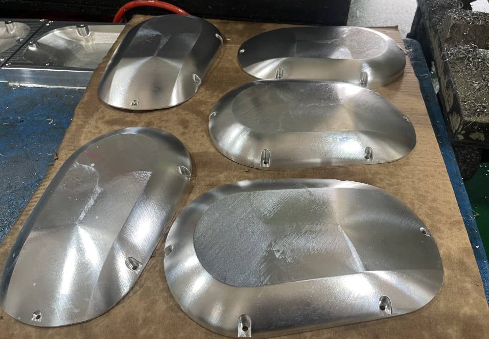
One of the subtle challenges in the parts shown above is the wall thickness. Based on the scale, the walls of the cylindrical section appear relatively thin compared to the overall height.
In CNC milling, thin-walled aluminum acts like a tuning fork. As the cutter engages the material, the wall wants to vibrate. This vibration causes “chatter,” which leaves ugly resonance marks on the surface and can even push the dimensions out of tolerance.
To achieve the clean, mirror-like finish you see in the photo, we employ specific strategies:
- High-Helix End Mills: These tools shear the material at a steeper angle, directing cutting forces vertically (into the spindle) rather than horizontally (against the thin wall).
- Adaptive Clearing: We maintain a constant chip load to prevent sudden spikes in tool pressure.
- Finishing Passes: We leave a small amount of stock (0.1mm) for a final, high-speed “spring pass” that barely touches the material, ensuring a pristine surface.
The Unseen Engineering: Packaging and Logistics
If you look at the photo again, you will notice the parts are sitting in a custom-molded plastic tray (blister pack). This is not an afterthought; it is a quality assurance requirement.
Aluminum is a soft metal. If we were to throw these parts into a bin together, they would scratch and dent each other during transport. This “part-on-part” damage is a leading cause of rejection in cosmetic parts.
Furthermore, these parts appear to be in their “as-machined” state. Before they go to surface finishing—such as clear or black anodizing—the surface must remain uncontaminated. Oils from human hands or dust can affect the anodizing consistency. The tray system ensures that once the part passes the Final QC check, it is not touched again until it reaches your assembly line or the plating tank.
Why Rapid Model for Your Production Run
At Rapid Model, we understand that a drawing is just a request; the physical part is the reality. Whether you are in the US or Europe, you need a partner in Shenzhen who acts as an extension of your own engineering team.
We combine high-speed 5-axis equipment with rigorous ISO 9001 quality management systems. We don’t just “cut metal.” We analyze your GD&T, design custom fixtures for repeatability, and engineer the packaging to ensure your parts arrive exactly as they left our machine.
Are you ready to scale your project from a single prototype to a consistent batch production run?
[BUTTON: Get A Free Quote -> https://sheerypauline.com/contact/]