In the world of procurement and mechanical design, there is a misconception that surface finish is merely the “final touch”—a cosmetic decision made after the hard engineering work is done.
I strongly disagree.
As a Sales Engineer here at Rapid Model, I see hundreds of RFQs weekly. The most successful projects are those where the finish is considered during the DFM (Design for Manufacturing) phase. The image above—a set of custom anodized aluminum CNC parts we recently produced—is a perfect case study. It demonstrates how precision milling, bead blasting, and electrochemical coloring work together not just to look good, but to solve specific engineering challenges.
Let’s break down the manufacturing logic behind these vibrant components.
Visual Analysis: Deconstructing the Parts
Looking at the photo of these blue components, a trained eye sees more than just color. We see specific machining strategies and material behaviors. Let’s analyze the three distinct categories of parts shown in the set.
1. The Multi-Pocket Housing (Left)
The long block on the left features four large, deep counterbored pockets with central boss features.
- The Challenge: Machining deep pockets in Aluminum 6061 requires careful toolpath planning to evacuate chips. If chips recut, they ruin the surface finish.
- The Feature: Notice the side holes. These imply this part likely required CNC machining services on a 4-axis or 5-axis machine to reach multiple faces without re-fixturing, ensuring the perpendicularity of those side ports relative to the main pockets.
2. The Slotted Mounting Plate (Center)
The central piece is a long, thin plate featuring a complex array of oblong slots and drilled holes.
- The Challenge: Stress relief. When you remove significant material from one side of a long, thin aluminum bar (like milling those slots), the internal material stresses release, causing the part to bow or warp.
- The Solution: To keep this flat, we likely utilized a “flip-flopping” machining strategy—removing small amounts of material from alternating sides—or performed a stress-relief heat cycle before the final finishing pass.
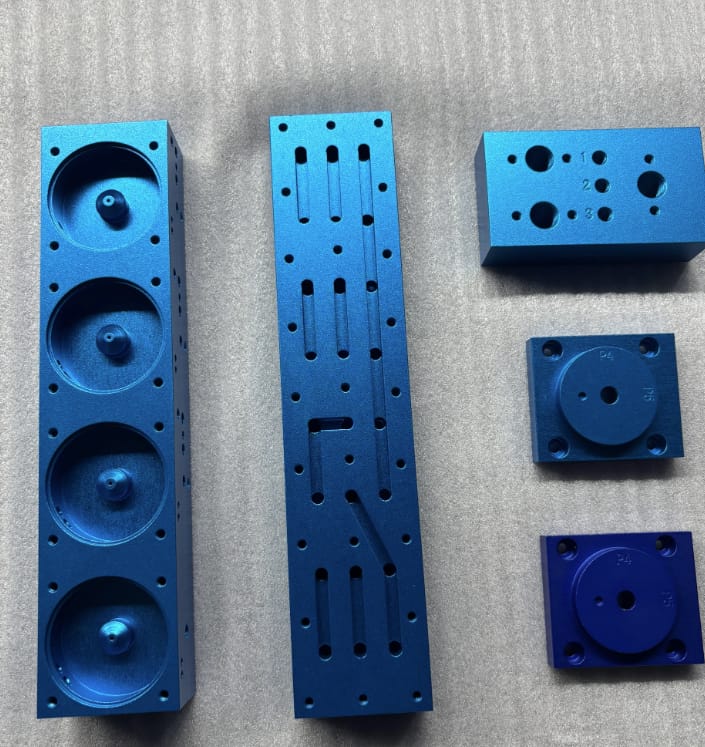
3. The Numbered Blocks (Right)
The smaller blocks feature engraved numbers (1, 2, 3) and text (P4, P5).
- The Detail: These aren’t laser marked; they are CNC engraved. You can tell by the depth. This is crucial for parts that might undergo heavy handling or abrasion where surface printing would wear off. The anodizing then coats the inside of the engraving, protecting the text from corrosion.
The Surface Finishing Trinity: Machining, Blasting, Anodizing
Achieving the specific “electric blue” matte finish seen in the photo involves a strict three-step protocol. If one step fails, the part is scrap.
Step 1: Precision Milling (Ra 1.6 – 3.2)
Before any finish is applied, the surface roughness (Ra) must be consistent. Any deep tool marks or chatter from the mill will show through the anodizing. We aim for a standard machined finish before moving to the blasting cabinet.
Step 2: Bead Blasting (The Matte Effect)
The prompt mentions a “matte texture.” This is achieved via bead blasting, typically using glass beads or aluminum oxide media (usually #120 grit).
- Why do it? Blasting removes minor machining lines and creates a uniform, non-directional surface.
- The Risk: Blasting removes material (approx 0.005mm – 0.01mm). For press-fit holes (like the central bores in the image), we must mask the holes or ream them after blasting to ensure tolerances are held.
Step 3: Type II Sulfuric Anodizing
The blue color isn’t paint. It is an anodic layer grown from the aluminum itself, then dyed.
- Process: We submerge the parts in a sulfuric acid bath and run an electric current through them. This opens “pores” in the aluminum oxide layer.
- Coloring: We dip the porous part into a blue organic dye. The dye molecules sit inside the pores.
- Sealing: The pores are sealed in boiling water, locking the color in.
For a deeper look at how we manage these textures, visit our guide on Surface Finishing.
Engineering Function: Why Color Code?
The social media post asks: Does color coding actually help with workflow efficiency?
The answer is a definitive yes. In complex assembly lines or automated machinery, color-coded anodized aluminum CNC parts serve as visual indicators (Poka-Yoke).
- Blue components might indicate pneumatic fixtures.
- Red components often signal safety guards or “remove before flight” tooling.
- Gold/Clear might indicate standard structural brackets.
This reduces assembly errors and speeds up maintenance. If a technician sees a blue part where a red one should be, they know immediately something is wrong without measuring.
Managing Tolerances with Anodizing
One of the most common questions I get from US engineers is: “How does anodizing affect my tight tolerances?”
Standard Type II anodizing adds approximately 5 to 15 microns (0.0002″ – 0.0006″) to the surface.
- For +/- 0.1mm tolerances: The layer thickness is negligible.
- For H7/H6 bore tolerances: This is critical.
- The Rapid Model Fix: We either mask the critical bores (keeping them raw aluminum) or we machine the features slightly oversized so that after the anodizing layer builds up, the final dimension lands perfectly in the middle of the tolerance zone.
Why Rapid Model for Your Custom Parts?
Whether you are in the Rapid Prototyping phase or moving to low-volume production, consistency is key.
At Rapid Model, we don’t just “dip and ship.” We verify the alloy (usually AL6061-T6 or AL7075-T6) to ensure the anodizing color will be consistent, as different alloys react differently to the dye. We check the Ra value after bead blasting, and we use CMM inspection to verify that the added thickness of the coating hasn’t pushed your parts out of spec.
The parts in the image represent what we do best: complex geometry, tight tolerance control, and premium cosmetic finishing.
Conclusion
Industrial parts do not have to be boring. In fact, when you utilize processes like bead blasting and anodizing, you are adding surface hardness, corrosion resistance, and operational clarity to your design.
Are you designing a complex assembly that requires color-coding or high-end surface treatment? Don’t leave the finish to chance. Let’s discuss your DFM requirements today.
[Call to Action Code]
[BUTTON: Get A Free Quote -> https://sheerypauline.com/contact/]