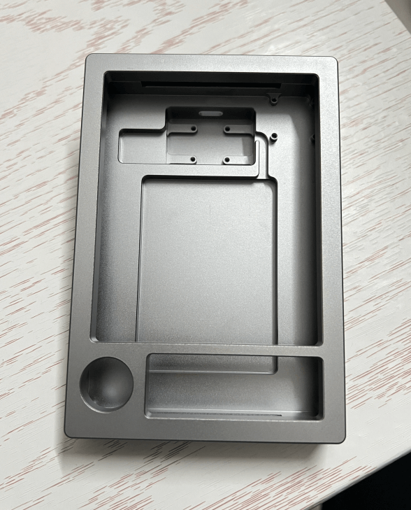
When I look at a part like the aluminum chassis shown above, I don’t just see a metal box. I see a series of deliberate engineering decisions regarding tool paths, chip evacuation, and material stress relief.
Whether you are designing a custom mechanical keyboard case, an industrial controller, or an aerospace enclosure, the principles of machining a high-quality CNC aluminum housing remain the same. Today, we are going to dive deep into the technical specifications of the part in the photo and explore how we achieve this level of precision at Rapid Model.
Table of Contents
- Visual Analysis: Deconstructing the Part
- Material Selection: Why 6061-T6 Reigns Supreme
- The Challenge of Thin Walls and Deep Pockets
- Surface Finishing: The Science of the “Matte Look”
- The Rapid Model Advantage
Visual Analysis: Deconstructing the Part
Let’s look closely at the image provided. This is a classic example of a “unibody” housing, likely milled from a solid billet of aluminum.
1. Internal Geometry and Weight Reduction
The most striking feature is the internal pocketing. You will notice distinct compartments: a large central cavity (likely for a battery or main PCB), a complex upper section with mounting bosses, and a lower section with a circular recess.
This isn’t just about creating space; it is about lightweighting. By removing substantial material volume while leaving structural ribs, the designer has maximized the strength-to-weight ratio. The challenge here is maintaining rigidity. If you remove too much material incorrectly, the floor of the housing will warp or “oil can” (pop in and out) under stress.
2. Precision Mounting Points
Notice the small bosses (standoffs) in the upper pocket. These require precise CNC machining services to ensure the threaded holes are perfectly perpendicular to the floor. Even a 0.5-degree deviation here can cause PCB misalignment during assembly.
Material Selection: Why 6061-T6 Reigns Supreme
Based on the grain structure and the finish shown in the photo, this part is almost certainly manufactured from Aluminum 6061-T6 (or possibly 6063).
For product designers in the US and Europe, 6061 is the industry standard for a reason:
- Machinability: It chips well, allowing for high material removal rates (MRR) without gumming up the cutter.
- Thermal Conductivity: Essential for electronics housings to dissipate heat generated by internal components.
- Anodizing Potential: It accepts surface treatments exceptionally well (more on this later).
If this were a prototype intended for stress testing, we might suggest 7075 aluminum for higher tensile strength, but for general electronics enclosures, 6061 offers the best balance of cost and performance.
The Challenge of Thin Walls and Deep Pockets
The part in the image features relatively thin walls separating the deep pockets. From a machinist’s perspective, this presents specific challenges that we solve daily at Rapid Model.
1. Vibration and Chatter
As the wall gets thinner, it becomes less stable. A high-speed end mill can cause the wall to vibrate, resulting in “chatter marks”—an ugly, wavy surface finish that ruins the aesthetic and dimensional accuracy.
To combat this, we utilize:
- Trochoidal Milling: A strategy where the tool moves in circular loops rather than straight lines, reducing the load on the cutter and the part.
- Variable Helix End Mills: These tools break up harmonic vibrations.
2. Chip Evacuation
In the deep rectangular pockets shown in the photo, chips can easily get trapped. If the cutter runs over old chips, it mars the surface finish. We use high-pressure coolant systems and air blasts to ensure the cutting zone remains clear, ensuring the floor of the pocket is as smooth as the exterior.
3. Rapid Iteration
Before committing to a production run of 1,000 units, we always recommend rapid prototyping. We can machine a single unit in as little as 3 days to verify that the wall thickness provides enough structural integrity for your specific application.
Surface Finishing: The Science of the “Matte Look”
The caption mentions a “matte silver look.” In the photo, the surface is uniform, non-reflective, and clean. This is not how the part looks immediately after CNC machining. As-machined aluminum has visible tool marks and a shiny, scratched appearance.
To achieve the finish in the image, we apply a specific surface finishing workflow:
- Deburring: Manual or tumble deburring to remove sharp edges.
- Bead Blasting: We blast the part with glass beads (typically #120 grit) at high pressure. This creates a uniform, matte texture and hides minor machining lines.
- Anodizing (Type II): The part is submerged in an electrolytic acid bath. This builds a protective oxide layer that prevents corrosion and hardens the surface. The “Silver” or “Clear” color comes from the natural oxide layer, though we can dye it black, blue, or red during this stage.
Pro Tip: For cosmetic parts, always specify the Ra (Roughness Average) value. A standard bead blast typically yields an Ra of 1.6µm to 3.2µm.
The Rapid Model Advantage
Why do Procurement Managers and Engineers choose Rapid Model for parts like this?
- ISO 9001 Certified: We don’t guess; we measure. Every housing undergoes CMM (Coordinate Measuring Machine) inspection to verify tolerances.
- Capacity: Whether you need 1 prototype or 10,000 production units, our facility in Shenzhen is equipped with 3-axis, 4-axis, and 5-axis CNC machines to handle complex geometries without multiple setups.
- DFM Support: We don’t just print what you send. If we see a sharp internal corner that requires a specialized EDM process (increasing cost), we will suggest a small fillet radius to allow for standard milling (saving cost).
Conclusion
The CNC aluminum housing pictured above is a perfect example of how internal precision drives external quality. By selecting the right alloy, controlling tool paths to manage thin-wall vibration, and applying a professional bead-blast finish, we transform raw metal into a premium product.
Are you working on a mechanical enclosure that requires this level of attention to detail?