In the world of high-stakes manufacturing, 5-axis impellers and complex aerospace manifolds often get all the glory. However, any seasoned mechanical engineer or procurement manager knows the truth: projects usually fail because of the simple parts.
A standard mounting bracket with a slightly off-center hole, a burr that interferes with mating surfaces, or a thread that strips during final assembly can halt a production line just as effectively as a failed engine block.
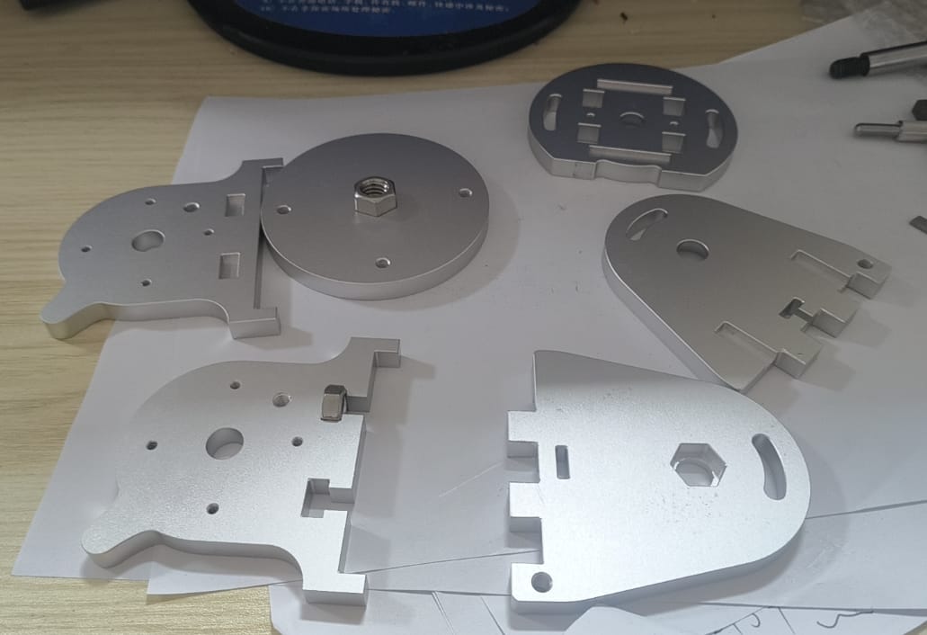
At Rapid Model, we treat standard structural components with the same rigor as complex geometries. Today, I want to break down the engineering reality behind the “simple” Aluminum 6061 mounting plates shown in the image above, and why “simple” implies zero room for error.
- The Engineering Reality of “Simple” Parts
- Visual Analysis: Deconstructing the Image
- Material Selection: Why 6061-T6 Remains King
- Surface Finishing: Raw vs. Bead Blasted
- The Rapid Model Quality Standard
The Engineering Reality of “Simple” Parts
When we receive a STEP file for a mounting plate, we aren’t just looking at the geometry; we are looking at the intent. For internal structural parts, three factors determine success or failure:
1. Edge Consistency and Deburring
Sharp edges are a liability. They cut wiring, injure assemblers, and prevent proper seating of mating parts. In CNC machining services, edge breaking is often where cost-cutting shops fail. They rely on manual filing, which is inconsistent. We utilize automated tumbling or precise C-axis chamfering (typically 0.2mm to 0.5mm) to ensure every edge is uniform.
2. Thread Integrity
A stripped thread on a chassis plate can ruin a $5,000 sub-assembly. We don’t guess with threads.
- Process: We use roll forming taps for aluminum where possible to compress the material rather than cut it, increasing thread strength.
- Validation: Every threaded hole is checked with calibrated Go/No-Go gauges. If the “No-Go” enters, the part is scrapped. No exceptions.
3. Flatness and GD&T
Mounting plates are the foundation of your assembly. If the plate is bowed due to internal material stress release during machining, your sensors or motors will be misaligned. We utilize stress-relieved plates and specialized vacuum fixtures to maintain flatness tolerances within +/- 0.05mm over 100mm spans.
Visual Analysis: Deconstructing the Image
Let’s look closer at the photo from our shop floor. These aren’t just generic scraps of metal; they showcase specific machining challenges.
- Complex Profiles & Thin Walls: Several of these plates feature irregular outer contours and internal slotting. Notice the thin sections between the outer edge and the internal cutouts. Machining this requires careful toolpath planning to avoid chatter or vibration, which would result in poor surface finish or dimensional inaccuracy.
- Hexagonal Features: One plate (bottom right) features a hexagonal pocket. Since a round end mill cannot cut a sharp internal corner, this feature likely requires a secondary broaching operation or a very small radius relief (dog-bone fillet) depending on the mating part’s requirements.
- Inserted Hardware: You can see a press-fit nut installed in the top-center circular plate. This highlights a critical value-add: Light Assembly. We don’t just machine; we install PEM nuts, helicoils, and standoffs. This ensures that when the part arrives at your facility in Europe or the US, it is ready for immediate integration.
Material Selection: Why 6061-T6 Remains King
These parts are machined from Aluminum 6061-T6. This is the bread and butter of the industry for good reason:
- Machinability: It chips well, allowing for high feed rates and reduced cycle times, which lowers your unit cost.
- Strength-to-Weight: With a yield strength of roughly 276 MPa, it is sufficient for almost all electronic enclosures, robotics brackets, and automation jigs.
- Anodizing Potential: If you need corrosion resistance or color coding later, 6061 takes Type II and Type III anodizing exceptionally well.
However, for early-stage validation, we often recommend our rapid prototyping services. We can machine a single unit in 6061 to verify fit before you commit to a 500-unit production run.
Surface Finishing: Raw vs. Bead Blasted
The social media post poses a question: Do you prefer a raw machined finish or bead blasted?
Looking at the parts in the photo, they have been Bead Blasted. You can tell by the uniform, matte grey texture that diffuses light.
- Raw Machined (As-Milled): Shows tool marks (swirls). It is cheaper and offers tighter dimensional control because you aren’t removing/compressing surface material with media. Best for surfaces that are hidden or require precise flatness.
- Bead Blasted: Uses glass beads or sand to bombard the surface. It hides minor tool marks and scratches from handling. It provides a professional, uniform aesthetic that implies “finished product” rather than “prototype.”
For most external or visible internal parts, we recommend bead blasting followed by clear or black anodizing to prevent oxidation. Learn more about our options for surface finishing.
The Rapid Model Advantage
Why do procurement managers in the USA and Europe trust Rapid Model with these “simple” parts?
It comes down to Process Reliability.
Simple parts are often ordered in higher volumes (100–1000+ units). At that volume, consistency is key. We operate under strict ISO 9001:2015 standards. Whether we are machining 5 parts or 5,000, our setup sheets, tool lists, and inspection reports remain consistent.
We understand that a delay on a mounting bracket is just as damaging as a delay on a complex housing. We quote fast, we machine accurately, and we ship on time.
Ready to Optimize Your Supply Chain?
Don’t let “simple” parts become complex problems. Whether you need a single prototype or a full production run of aluminum mounting plates, my team is ready to review your STEP files.