In the world of industrial procurement and mechanical design, it is easy to glance at a Bill of Materials (BOM), see a “Stainless Steel T-Connector,” and treat it as a commodity. However, as anyone who has dealt with a high-pressure system failure knows, small components carry massive responsibility.
At Rapid Model, we process thousands of precision turned and milled parts annually. The difference between a functional prototype and a production-grade component often lies in the invisible details: the perpendicularity of a port, the integrity of a thread, and the microstructure of the material after machining.
This article dives into the technical realities of CNC machining stainless steel components for fluid control systems, analyzing the specific challenges of geometry, sealing, and finishing.
Table of Contents
- The Engineering Challenge: It’s Not Just a Cylinder
- Visual Analysis: Machined vs. Welded Assemblies
- Material Science: Why Stainless Steel Fights Back
- Ensuring Leak-Proof Performance
- The Rapid Model Advantage
The Engineering Challenge: It’s Not Just a Cylinder
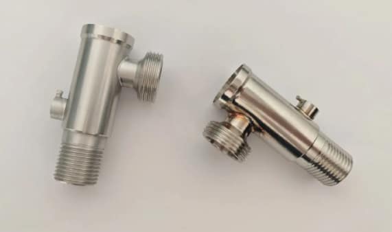
When designing fluid control parts—like the housings shown in the header image—the primary challenge is rarely the main diameter. The challenge is the relationship between features.
In the image provided, we see a T-style housing with a main body and a perpendicular threaded port. To the untrained eye, this is simple plumbing. To a machinist, this is a strict exercise in Geometric Dimensioning and Tolerancing (GD&T).
Perpendicularity and Concentricity
The side port must be perfectly perpendicular (90°) to the main bore. Even a deviation of 0.5 degrees can cause misalignment in the mating pipework, leading to stress on the seals and eventual leakage.
Achieving this requires advanced CNC machining services. We typically utilize multi-axis Mill-Turn centers for parts like these. By rotating the workpiece and engaging live tooling, we machine the side port without removing the part from the chuck. This “Done-in-One” approach maintains tighter concentricity compared to moving the part from a lathe to a mill, which introduces fixturing errors.
Visual Analysis: Machined vs. Welded Assemblies
Let’s take a closer look at the two components from the image. They tell two different manufacturing stories.
The Part on the Left: The Machined Ideal
The component on the left features a consistent, matte finish (likely bead blasted or as-machined). The transition from the main body to the side port is crisp.
- Feature Note: Notice the small boss/pin protruding from the side. This feature cannot be created on a standard 2-axis lathe. It requires 4-axis or 5-axis milling capabilities to carve away the material around that pin.
- Advantage: Integral machining from a solid block or a near-net-shape forging ensures maximum structural integrity. There are no heat-affected zones (HAZ) to worry about.
The Part on the Right: The Welded Reality
The component on the right has a shinier, polished finish, but more importantly, it shows discoloration at the junction of the T-section. This “heat tint” suggests a welding operation (likely TIG or Laser welding) joining two separate turned parts.
- The Challenge: While welding can reduce raw material waste, it introduces thermal distortion. The heat can warp the threads or ovalize the main bore.
- Finishing Requirement: To make a welded part viable for high-purity applications, aggressive surface finishing is required to remove oxidation and passivate the surface against corrosion.
Material Science: Why Stainless Steel Fights Back
Whether you are using SS304 for general corrosion resistance or SS316L for marine and medical applications, stainless steel is notorious for work hardening.
If the CNC cutter dwells in one spot for too long, or if the feed rate is too slow, the material hardens instantly. This creates two problems for fluid control parts:
- Tool Deflection: The tool pushes away from the hard surface, causing the bore to be undersized or tapered.
- Poor Surface Finish: Instead of cutting, the tool rubs, leaving micro-tears on the sealing surfaces.
For rapid prototyping, we often recommend specific annealing processes or utilizing free-machining grades (like 303) if welding is not required, to lower costs and speed up delivery. However, for production pressure vessels, we stick to the specified 316/304 grades and utilize high-pressure coolant systems to manage heat and chip evacuation.
Ensuring Leak-Proof Performance
The ultimate test of these components is the seal. The image displays external threads (likely NPT or BSPP) on the bottom and side ports.
Thread Quality
In fluid power systems, a “burr” is a disaster waiting to happen. A microscopic metal shard left in a thread can:
- Prevent the mating part from seating fully.
- Break off and travel downstream, destroying pumps or sensors.
At Rapid Model, we do not rely solely on machine deburring. For critical fluid components, we implement a thermal deburring process or manual microscopic inspection to ensure the “start” and “stop” of the thread are clean.
Sealing Surfaces
Look at the smooth shank above the threads on the left part. This is likely an O-ring sealing surface. The surface roughness (Ra) here is critical. If it is too rough, the O-ring abrades. If it is too smooth, the O-ring may slide or extrude under pressure. We typically aim for an Ra 0.8µm to 1.6µm finish for static O-ring seals.
The Rapid Model Advantage
Why do procurement managers in the US and Europe trust Rapid Model with these “small but responsible” parts?
- ISO 9001 Certified Processes: We trace our material heat numbers from the mill to the machine. You know exactly what alloy you are getting.
- 5-Axis Capability: We reduce setup times and geometric errors by machining complex intersections in a single setup.
- Comprehensive Finishing: From electropolishing for high-purity flows to passivation for corrosion resistance, we handle the post-processing in-house or with trusted partners.
If your engineering team is struggling with leakage rates, thread galling, or perpendicularity issues in your current supply chain, it is time to look at the manufacturing process itself.