In the world of precision manufacturing, geometric primitives—cubes, cylinders, and flat planes—are straightforward. They are the “bread and butter” of any machine shop. However, the real test of a manufacturer’s capability arises when a design moves away from straight lines and embraces organic, compound curvature.
For product designers and mechanical engineers, these shapes are essential for ergonomics and aerodynamics. For the machinist, they present a unique set of challenges regarding tool access, surface finish, and dimensional accuracy.
At Rapid Model, we frequently bridge the gap between complex CAD splines and physical metal. Today, I want to break down a recent project involving organic aluminum covers to explain the “how” and “why” behind our CNC machining services.
(Table of Contents Placeholder)
Visual Analysis: Deconstructing the “As-Machined” Part
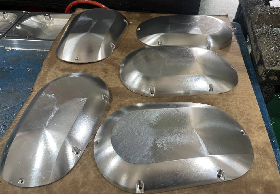
Let’s take a close look at the image from our factory floor. What you are seeing is a batch of five aluminum housing covers, fresh off the machine and sitting on the inspection bench.
To the untrained eye, they look like simple curved metal pieces. To an engineer, the details tell a story of the machining strategy:
- Compound Curvature: These aren’t simple 2D radii. The surface curves in two directions simultaneously (convex geometry). This requires 3D surface profiling, where the CNC machine interpolates X, Y, and Z axes (and likely A and B axes) simultaneously.
- Tool Path Signatures: Notice the faint, rhythmic lines running across the surface. These are “scallop” marks left by a ball-nose end mill. They are consistent and uniform, indicating a stable machine setup and a constant step-over rate.
- Perimeter Features: The edges feature recessed mounting holes (counterbored or countersunk) drilled into the curved surface. This requires the cutting tool to approach the part at a specific normal vector—a classic application for 5-axis CNC machining.
- Batch Consistency: All five parts show identical surface textures and light reflections. This repeatability is critical in B2B procurement; the first part must match the five-hundredth.
The Technical Challenge: 3-Axis vs. 5-Axis for Organic Shapes
Why do we emphasize 5-axis machining for parts like these?
If you attempted to machine these covers on a standard 3-axis mill, you would face significant limitations. A 3-axis machine can only move linearly. To cut a curve, it moves in tiny steps (interpolation). However, as the tool moves down the steep sides of the cover, the contact point of the tool changes, often rubbing against the non-cutting shank of the tool or requiring an impossibly long tool stick-out to avoid collisions.
The 5-Axis Solution:
By utilizing a 5-axis setup (likely a trunnion table configuration), we can tilt the workpiece. This allows us to:
- Maintain Optimal Cutting Angles: We keep the cutting flutes engaged rather than the bottom center of the ball mill (where cutting speed is effectively zero).
- Shorten Tool Length: We can use shorter, more rigid tools because the head or table tilts away from the part, reducing vibration (chatter).
- Single Setup Machining: We can machine the top profile and the side mounting holes in one operation, ensuring perfect concentricity and positional tolerance.
Surface Profiling: The Science of the “Step-Over”
In the social media post, I mentioned that “some engineers love seeing the tool paths.” Let’s define what those are technically.
When machining a 3D surface, the cutter moves back and forth (raster) or spirals (waterline). The distance the tool moves over for the next pass is called the step-over.
- Large Step-Over: Faster machining time, but leaves high “scallops” (ridges) that require heavy sanding.
- Small Step-Over: Increases cycle time significantly, but results in a near-smooth surface with a low Ra (Roughness Average).
The parts in the image display a balanced strategy. The step-over is tight enough to maintain geometric accuracy but leaves a slight texture that is easily removed in the next stage. This is a cost-effective approach for rapid prototyping, where you don’t want to pay for hours of unnecessary machine polishing if the part is going to be manually finished anyway.
From “As-Machined” to “Showroom Ready”
The debate of “Tool Paths vs. Glass Smooth” usually depends on the application.
- Internal Components: Tool marks are acceptable if they don’t affect fit or function.
- Consumer Facing: These usually require a cosmetic finish.
For the aluminum covers shown, the current state is “As-Machined.” To achieve a cosmetic look, we would proceed to our surface finishing department.
The workflow would look like this:
- Sanding: We manually or mechanically sand down the scallop peaks to create a uniform matte surface.
- Bead Blasting: Shooting glass beads or ceramic media to homogenize the surface texture.
- Anodizing: Electrochemical passivation to protect the aluminum and add color (e.g., Clear or Black Type II Anodizing).
Because the underlying machining was done with high precision (consistent step-over), the finishing team spends less time correcting geometry and more time perfecting the aesthetic.
Material Matters: Aluminum 6061 vs. 7075
While I can’t disclose the exact alloy of this client’s project, parts like these are typically machined from Aluminum 6061-T6 or 7075-T6.
- 6061: The industry standard. It offers excellent corrosion resistance and weldability. It is softer, meaning it machines faster but can be “gummy” if the feeds and speeds aren’t dialed in, leading to poor surface finish.
- 7075: Much harder and stronger (comparable to some steels). It actually machines cleaner than 6061 because the chip breaks away cleanly, leaving a superior finish right off the machine. However, it is more expensive and harder to anodize consistently.
The Rapid Model Advantage
At Rapid Model, we don’t just load a CAD file and hit “Run.” We analyze the geometry to determine the most efficient machining strategy.
Whether you are a procurement manager looking for a batch of 50 or a product designer needing a single complex prototype, our ISO 9001 certified process ensures:
- DFM Feedback: We warn you if a radius is too tight or a wall is too thin before we cut metal.
- Precision Tooling: We use high-quality carbide end mills to minimize tool deflection on organic shapes.
- Verification: We use CMM (Coordinate Measuring Machines) to verify that the complex curves on the physical part match your digital model.
Conclusion
Organic shapes in metal are unforgiving. They expose every inefficiency in a machine shop’s process. The covers shown in the image demonstrate that with the right 5-axis equipment and a skilled programming team, complex curvature can be executed with precision and consistency.
Are you designing parts with complex surfaces? Don’t let manufacturing limitations dictate your design intent.