In the world of mechanical design, a single component is rarely the end goal. The true test of a manufacturer isn’t just how well they can mill a block of aluminum, but how well they can orchestrate a Precision CNC Assembly.
I often see designs that look flawless in CAD, but fail on the assembly bench. Why? Because of tolerance stacking and the unpredictable variables of surface finishing.
Recently, our team at Rapid Model completed a project that perfectly illustrates the harmony between design intent and manufacturing execution. It is a multi-axis adjustable mount—likely for optical or laser alignment applications—that required tight coordination between CNC milling, surface finishing, and final assembly.
In this post, I will break down the engineering challenges of this specific part and how we solved them.
Table of Contents
- Visual Analysis: Deconstructing the Mount
- The Hidden Challenge: Anodizing & Tolerance Stacking
- The “Feel” Factor: Knurling and Haptics
- Why Rapid Model is Your Assembly Partner
Visual Analysis: Deconstructing the Mount
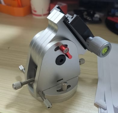
Looking at the finished assembly in the image above, we are dealing with a classic high-precision mechanism. The primary material is almost certainly Aluminum 6061-T6, chosen for its excellent strength-to-weight ratio and anodizing receptivity.
Here is what stands out from a manufacturing perspective:
- Complex Geometry: The main housing features a curved profile with side pockets milled to reduce weight without sacrificing rigidity. This requires 4-axis or 5-axis CNC machining services to reach the undercut areas and side mounting holes in a single setup, ensuring geometric accuracy.
- Surface Finish Consistency: The part features a uniform bead-blasted finish (likely Glass Bead #120) prior to anodizing. This removes tool marks and provides that premium, non-reflective matte look essential for optical environments.
- Multi-Component Integration: This isn’t a monolith. It involves a clear anodized body, a black anodized top plate (likely a dovetail interface), and a red anodized locking lever.
- Hardware Integration: Note the integration of the green bubble level into the adjustment knob. This requires a precise bore—too loose, and the level falls out; too tight, and the glass vial cracks during press-fit.
The Hidden Challenge: Anodizing & Tolerance Stacking
The most difficult aspect of this project was not the milling itself, but managing the multi-color anodizing while maintaining assembly fits.
When you anodize aluminum, you are growing an oxide layer on the surface. For standard Type II anodizing, this adds approximately 5 to 15 microns (.0002” to .0006”) of thickness per side. In a complex assembly like this, where a black plate slides into a clear body, and a red lever locks a rotating shaft, those microns add up. This is known as tolerance stacking.
How We Manage This at Rapid Model:
- Pre-Process Compensation: We don’t just cut to the print dimensions. If we know a bore needs to accept a precision shaft after anodizing, we machine the bore slightly oversized (by the exact thickness of the anticipated coating) during the CNC stage.
- Masking Strategies: For grounding points or extremely tight tolerance threads, we utilize high-temperature masking plugs to keep those surfaces raw aluminum, ensuring the fit remains unchanged by the chemical process.
- Batch Consistency: To ensure the “Red” on the lever matches the client’s brand color exactly, we run these small batches simultaneously to control the dye saturation levels.
For engineers developing new hardware, we often suggest starting with rapid prototyping of the assembly in raw aluminum to verify the mechanics before introducing the variable of surface finishing.
The “Feel” Factor: Knurling and Haptics
In the social media post regarding this part, I mentioned that “The knurled knobs need to rotate smoothly with zero play.”
This refers to haptics—the tactile feedback the user gets when operating the device. For an optical mount, the adjustment needs to be smooth but firm. If the threads are too loose (Class 1A fit), the mount will wobble, rendering the optical alignment useless. If they are too tight, the user fights the mechanism.
The Knurling Detail
The diamond knurling on the adjustment knobs (seen on the right and bottom left of the image) serves two purposes:
- Grip: It allows for fine adjustments with fingertips.
- Aesthetics: It adds a premium industrial look.
However, knurling is a deformation process. It pushes material outward, increasing the outer diameter of the stock. At Rapid Model, we control this carefully. We often use cut-knurling tools rather than form-knurling for precision parts like this, as it creates cleaner points and puts less stress on the lathe spindle, resulting in better surface finishes.
Learn more about our various texturing and surface finishing options to see how we can elevate the look and feel of your parts.
Why Rapid Model is Your Assembly Partner
Many shops in China will machine your parts and ship them to you in a bag, leaving you to deal with the assembly headaches. Rapid Model is different. We view ourselves as an extension of your engineering team.
When we take on a Precision CNC Assembly project, we perform:
- ISO 9001 Certified QC: We check GD&T callouts on CMM machines before the parts even reach the assembly room.
- Fit Check: We physically assemble the unit (as seen in the photo) to verify that the movement is smooth and the locking mechanisms engage correctly.
- Hardware Sourcing: We source the off-the-shelf components (like the bubble level vial, springs, and stainless steel screws) so you receive a drop-in ready unit.
Whether you are building one complex prototype or 500 production units, the goal is the same: parts that look amazing and work perfectly right out of the box.
Ready to build your next mechanism?
Don’t let tolerance issues slow down your product launch. Send us your CAD files today, and let’s discuss how we can manufacture your design with harmony.