In the world of power transmission, vibration is the enemy. I have seen entire production lines in Europe and the US shut down simply because a coupling hub had a runout deviation of 0.05mm. When you are transferring high torque at high RPMs, “close enough” is a recipe for mechanical failure.
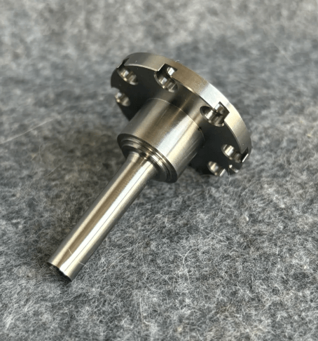
The image above—a heavy-duty coupling hub recently machined here at Rapid Model—is a textbook example of why precision geometry matters. It’s not just about removing metal; it’s about ensuring that every feature, from the keyway to the bolt circle, aligns perfectly with the rotational axis.
In this post, I want to break down the manufacturing engineering behind this part, specifically focusing on the debate between Broaching and Wire EDM for keyways, and why surface integrity is non-negotiable in CNC machining services.
[TOC Placeholder]
The Anatomy of a High-Torque Coupling Hub
Looking at the part shown in the header image, several features immediately stand out to a trained eye. This isn’t a standard “off-the-shelf” component; this is a custom-engineered solution designed for a specific load profile.
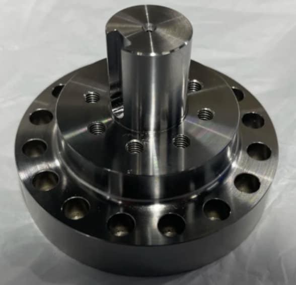
1. The Central Boss and Rotational Physics
The cylindrical boss housing the shaft bore is the critical datum structure. For a part like this, concentricity is the primary GD&T (Geometric Dimensioning and Tolerancing) requirement. If the outer diameter (OD) of the flange is not perfectly concentric to the inner diameter (ID) of the shaft bore, the resulting imbalance will destroy bearings downstream.
At Rapid Model, we typically achieve this by performing the turning operations for the ID and OD in a single setup on our multi-axis lathes. This ensures that the runout is kept within microns, far tighter than what is possible if the part were flipped or re-chucked.
2. The Keyway: Broaching vs. Wire EDM
The prompt mentioned the “crispness” of the keyway slot. This is the torque transfer point. If there is slop (play) here, the shaft will hammer against the hub during start/stop cycles, leading to fatigue failure.
The question was posed: Wire EDM or Broaching?
- Broaching: This is the traditional method for high-volume production. It is fast and cost-effective. However, broaching exerts massive physical force on the part, which can induce stress or slight deformation in thinner walls. It also struggles with hardened materials.
- Wire EDM (Electrical Discharge Machining): Looking at the sharp internal corners and the smooth finish inside the keyway in the image, my assessment is that this was likely finished via Wire EDM. Wire EDM is a non-contact process. It allows us to cut hardened steel without inducing thermal or mechanical stress. It achieves a near-perfect perpendicularity and can hold tolerances as tight as +/- 0.005mm.
For heavy-duty, high-precision custom parts like this, I almost always recommend Wire EDM to ensure that “zero-slop” fit.
Material Analysis and Surface Integrity
Based on the visual luster and the machining marks, this part appears to be manufactured from 316 Stainless Steel or a high-grade 4140 Alloy Steel.
The Challenge of Stainless Steel
If this is 316 SS, it presents specific machining challenges. Stainless steel has a tendency to work-harden if the cutter dwells too long. To get that clean, bright finish seen on the flange face, our operators must calculate precise feeds and speeds to shear the material cleanly rather than plowing it.
Surface Finish (Ra)
The face of the part is highly polished. In engineering terms, this looks like an Ra 0.8µm (32 µin) finish or better. Why does this matter?
- Sealing: If this face mates against a gasket or an O-ring, a rough surface will create leak paths.
- Bearing Pre-load: If this face sits against a bearing race, surface irregularities will lead to uneven loading.
Achieving this requires a final finishing pass with a specialized wiper insert or a secondary polishing operation. You can learn more about our specific standards for this in our Surface Finishing guide.
The Bolt Circle: Positional Tolerance
You will notice two distinct sets of holes on this flange:
- Inner Circle: Threaded (tapped) holes on the boss.
- Outer Circle: Counterbored through-holes on the flange.
The challenge here is True Position. The counterbored holes must align perfectly with the mating part. If the bolt circle diameter (BCD) is off by even 0.1mm, the assembly technicians will be forced to force the bolts in, stripping threads or creating stress risers.
We utilize CNC milling centers with probed verification. Before the drill even touches the metal, the machine probes the center bore to establish the exact zero point. This guarantees that the bolt pattern is perfectly centered around the axis of rotation.
From Prototype to Production
For procurement managers, the risk with parts like this is scalability. You might get one perfect sample, but can the factory replicate it 1,000 times?
When we handle rapid prototyping for coupling hubs, we use the exact same toolpaths and machines that we use for mass production. We don’t “hand-finish” a prototype to make it look good only to fail at volume.
If you are developing a new transmission system, I recommend ordering a functional prototype in the actual end-use material (e.g., 4140 Pre-hard). This allows you to test the torque limits and the fit of the keyway before committing to the full run.
The Rapid Model Advantage
At Rapid Model, we don’t just read the drawing; we analyze the application.
- ISO 9001 Certified: Our quality management system ensures traceability.
- CMM Inspection: For a part like this, we would provide a CMM (Coordinate Measuring Machine) report verifying the keyway width, bore diameter, and geometric concentricity.
- Speed: We understand that a missing coupling can stall an entire machine build.
Whether you need a single custom flange or 5,000 drive hubs, our engineering team in Shenzhen is ready to optimize your design for manufacturability.
Conclusion
The coupling hub in the image is more than just a piece of metal; it is a critical link in a kinetic chain. Achieving the perfect fit requires a deep understanding of CNC turning, Wire EDM nuances, and material science.
Don’t let poor tolerances compromise your machinery’s performance. Let’s discuss your technical requirements.