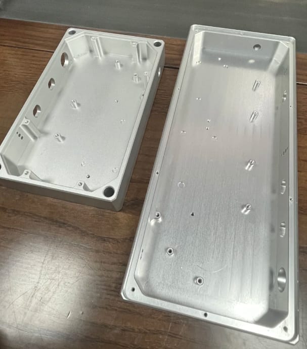
To the untrained eye, the image above shows two simple metal boxes. But to a mechanical engineer or a procurement manager sourcing precision parts, these components represent a minefield of potential manufacturing failures.
When you are designing custom housing for sensitive electronics, the enclosure does more than just hold parts together—it acts as a heat sink, an EMI shield, and a structural backbone. However, achieving the geometry seen in these photos—specifically the deep pockets and thin walls—is deceptively difficult.
At Rapid Model, we see thousands of designs like this annually. In this post, I’m taking you onto the shop floor to explain exactly how we tackle the challenges of CNC machined aluminum enclosures, ensuring that what you design in CAD is exactly what arrives at your loading dock.
Table of Contents
- Visual Analysis: More Than Just a Box
- The Enemy of Precision: Vibration and Chatter
- The Criticality of Standoff Flatness
- Surface Finishing: Preparing the Canvas
- Why Rapid Model for Electronics Housing
Visual Analysis: More Than Just a Box
Let’s look closely at the parts in the header image. These are likely machined from Aluminum 6061-T6, the industry standard for CNC machining services due to its excellent strength-to-weight ratio and anodizing capabilities.
Key Features Identified:
- Deep Pockets: The enclosure on the left features a significant depth-to-width ratio. Removing this much material (often 80-90% of the billet) releases internal material stresses, which can lead to warping if not managed correctly.
- Side Ports: You can see distinct circular and rectangular cutouts on the sidewalls. These require multi-axis machining (3+2 or full 5-axis) to access the sides without multiple setups that introduce tolerance stacking errors.
- Internal Bosses/Standoffs: The “islands” left inside the pocket are crucial for mounting the PCB. Their isolation makes them prone to deflection during the cut.
The Enemy of Precision: Vibration and Chatter
The most obvious challenge in machining the chassis shown above is wall-thickness management.
When an end mill engages with a thin wall (typically under 1mm or 0.040″), the wall itself can act like a tuning fork. As the cutter strikes the metal, the wall vibrates. This resonance causes “chatter”—a harmonic vibration that leaves ugly, distinct patterns on the surface and kills dimensional accuracy.
How We Solve It
We don’t just slow the machine down; we optimize the physics of the cut.
- Adaptive Clearing: We use trochoidal tool paths that maintain a constant tool load, reducing the shock on thin walls.
- Step-Down Strategy: Instead of cutting the full depth at once, we machine in steps (Z-level roughing) leaving a small amount of stock (0.1mm – 0.2mm) on the walls.
- Finish Passes: The final finishing pass is done at high RPM with a very low chip load to “kiss” the surface smooth without exerting enough cutting pressure to deflect the wall.
If you are in the rapid prototyping phase, we can often suggest slight design modifications—such as adding small fillets at the base of the walls—to drastically increase stiffness without affecting component fit.
The Criticality of Standoff Flatness
Look at the small internal pillars (standoffs) in the right-hand part of the image. These are not just mounting points; they are the reference plane for your Printed Circuit Board (PCB).
The Engineering Problem:
If these standoffs vary in height by even 0.1mm, tightening the screws will force the PCB to flex. A flexed PCB is a ticking time bomb. It puts stress on solder joints (especially BGA components), leading to micro-cracks and intermittent failures that are a nightmare to diagnose in the field.
The Manufacturing Solution:
To ensure all standoff tops are coplanar:
- We machine the floor and the tops of the standoffs in the same setup whenever possible.
- We verify flatness using CMM (Coordinate Measuring Machine) probes.
- We ensure the threads are tapped (or helical interpolated) perfectly perpendicular to the floor to prevent screw cross-threading.
Surface Finishing: Preparing the Canvas
The post mentions that the finish provides “tooth.” This is accurate. While the raw “as-machined” look has a certain industrial appeal, most commercial electronics enclosures require secondary processing.
The uniform matte texture seen in high-end audio equipment or medical devices is usually achieved through bead blasting. We blast the aluminum with glass beads or ceramic media to remove minor tool marks (like the ones visible on the floor of the right-hand part) and create a uniform, non-directional texture.
This texture is vital for surface finishing steps like Anodizing or Powder Coating.
- Anodizing (Type II or III): The blasted surface allows the anodic layer to form evenly, reducing the “glossy” spots that can occur on smooth machined surfaces.
- Powder Coat/Paint: The mechanical “tooth” ensures the coating adheres physically to the metal, preventing peeling or chipping during assembly.
Why Rapid Model for Electronics Housing
Sourcing custom aluminum enclosures is a balance of speed, cost, and geometric fidelity. At Rapid Model, we bridge the gap between prototype responsiveness and production consistency.
- Material Stability: We understand stress relief. For parts with heavy material removal, we utilize stress-relieving cycles to ensure the box doesn’t twist like a potato chip after it comes off the machine.
- 5-Axis Capability: Those side ports for USB and HDMI connectors? We machine them in a single setup to ensure they align perfectly with the PCB mounted inside.
- ISO 9001 Quality: Every batch goes through rigorous inspection to ensure thread gauges fit and wall thicknesses meet your GD&T requirements.
Whether you need a single prototype to validate thermal performance or 5,000 units for a product launch, we have the spindle capacity to deliver.
Ready to turn your CAD into a precision machined reality?