In the world of custom manufacturing, there is a distinct difference between making a “pretty part” and engineering a functional, high-precision component that happens to look beautiful.
Designers often chase the aesthetic—that liquid metal look or the perfectly reflective chrome surface. However, for the mechanical engineers and procurement managers I work with in the US and Europe, the priority is dimension. The conflict arises because high-gloss finishing is a subtractive process. It removes material.
If you don’t control that removal, you lose your tolerance.
Table of Contents
- The Paradox of Polishing and Precision
- Visual Analysis: What the Image Reveals
- The Hidden Challenge: Edge Definition vs. Material Removal
- Batch Consistency: The True Test of a Machine Shop
The Paradox of Polishing and Precision
Achieving a mirror finish (typically defined as a surface roughness of Ra 0.02μm to 0.05μm) is not merely about buffing a part until it shines. It is a calculated sequence of grinding, sanding, and polishing.
Here is the engineering problem: To remove machining marks (scallops) left by the CNC mill, you must abrade the surface. If a part has a tolerance of ±0.05mm, and your polishing team aggressively removes 0.03mm of material to smooth out a tool mark, you are dangerously close to scrapping the part.
Visual Analysis: What the Image Reveals
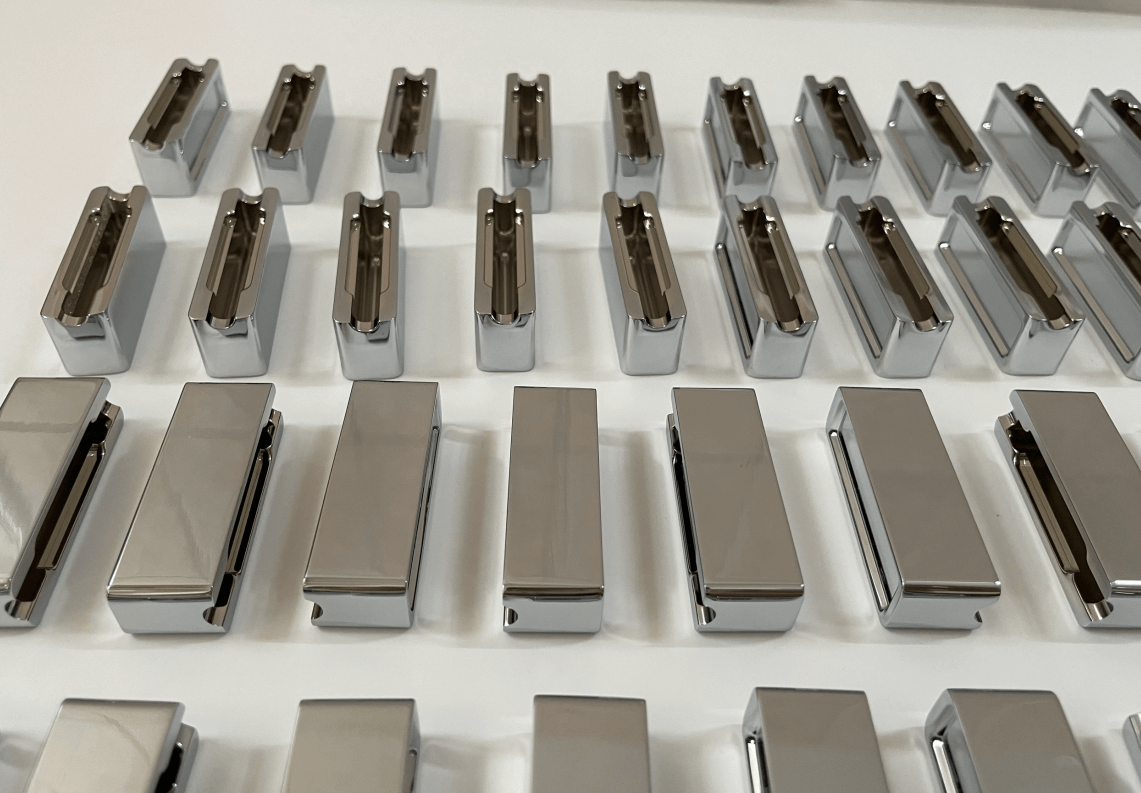
Let’s look strictly at the data provided by the photograph of our recent production run.
These components appear to be housing units, likely for a consumer electronic device or a medical instrument. Based on the luster and the color tone, the material is likely Stainless Steel 316L polished to a mirror shine, or perhaps Aluminum 6061 that has undergone chemical brightening and electroless nickel plating or chrome plating.
Key Observations:
- The Geometry: The parts feature a deep internal pocket with a stepped lip. Machining deep pockets requires long-reach tools, which introduces vibration (chatter). However, the reflection on the top faces is undistorted, indicating zero chatter marks were transferred from the milling stage.
- The Reflection: Notice the reflection of the adjacent parts in the side walls. It is crisp. This indicates “surface integrity.” There is no orange peel effect, and no porosity. Porosity is a common failure in die casting, but since these are CNC machined from solid billet, the material structure is dense and uniform.
- The Assembly Features: There are small holes and slots machined into the side. In a sloppy process, polishing compound would build up in these crevices, or the buffing wheel would round over the entry points. Here, they remain sharp.
The Hidden Challenge: Edge Definition vs. Material Removal
In my experience assisting clients with surface finishing, the number one defect in high-polish parts is “washed-out edges.”
When a manual polishing technician applies a part to a buffing wheel, the wheel naturally wants to wrap around the corners. This erodes the sharp edge, turning a defined radius into an organic, uneven slope. If this part needs to mate with a lid or another assembly component, that rounded edge creates a visible gap line that ruins the product’s premium feel.
How do we prevent this?
- Hard Masking: We use fixtures to cover critical edges during the tumbling or rough polishing phases.
- Controlled Pressure: We utilize specific polishing compounds that cut faster with less pressure, reducing the deformation of geometric features.
- CMM Verification: We don’t just look at the shine. We measure the geometry after polishing to ensure the material removal hasn’t altered the critical dimensions.
Batch Consistency: The True Test of a Machine Shop
The social media post associated with this image noted: “There is something oddly satisfying about a perfectly organized production run.”
This is an understatement. It is incredibly difficult to make 50 or 100 parts look exactly the same when manual finishing is involved. In rapid prototyping, making one “Golden Sample” is standard. But scaling that to a low-volume production run of 500 units requires strict Standard Operating Procedures (SOPs).
If Technician A buffs for 2 minutes and Technician B buffs for 3 minutes, your batch is inconsistent.
- Grit Progression: Defined steps (e.g., 400 grit -> 800 grit -> 1500 grit -> Diamond Paste).
- Time per Step: Strictly monitored.
- Visual Masters: Every station has a “Master Sample” for visual comparison under high-lumen inspection lights.
This ensures that the first part in the tray matches the last part in the tray, as seen in the photo above.
What Buyers Should Verify
Before placing an order, confirm material grade, tolerance-critical features, inspection methods, finishing limits, packaging, lead time, and applicable certifications with the selected manufacturing partner. SP Precision coordinates RFQ review, DFM communication, quotation, and supplier follow-up; project-specific production capabilities and certification documents are confirmed before order placement.
Ready to elevate your product quality?
If you are looking for a manufacturing partner who understands the balance between surface aesthetics and engineering tolerances, let’s talk. Send me your STEP files today, and let’s review the manufacturability of your design.